Simple robot arm controlled by ROS and MoveIt – Part 2
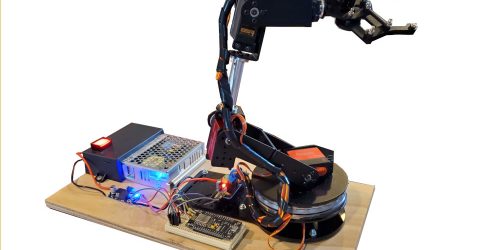
In the previous post I started describing my journey to learn ROS, and how it can be used to drive a robot arm. I have chosen a simple servo based robot arm so that I can focus on the software and spend less time designing and building joints and control systems. In my first post I built the robot arm, built a manual test rig, built a 3D model, developed a URDF file (XML description of the robot arm), installed ROS and built a simulation of the robot in ROS RViz.
To drive the robot arm, I decided to use MoveIt – a ROS package that is designed to drive a robot arm, using that latest in motion planning, robot manipulation, kinematics, control and navigation. MoveIt is clearly quite a bit more sophisticated than would normally be used on what is essentially a toy robot arm. However, it should provide a good learning platform which I can hopefully apply to a more sophisticated robot in the future. Like the rest of ROS, MoveIt seems quite complicated, but I only intend to use it to do the kinematic calculations, the motion planning and the robot control. So hopefully I will be OK, hear goes……
Install MoveIt
In the previous post I described how I installed ROS Noetic on Ubuntu 20.04.2 LTS which is running on a virtual machine on a Windows 10 PC. There is a very detailed website that describes how to install MoveIt, and I followed this quite faithfully. However, there are a couple of small changes I needed to make due to decisions I made in the previous post. I will highlight these changes in this post.
Click on this link to go to the MoveIt ‘Getting Started’ web page. This page assumes you have installed ROS and have catkin installed. It also states that you should create a workspace.
mkdir -p ~/ws_moveit/src

cd ~/ws_moveit/src
In the previous post I established a workspace ‘ws_servoarm’. So I replaced ‘ws_moveit’ with ‘ws_servoarm’ for the remainder of the process. There was no need to make a new directory, so I just moved to the existing src directory to proceed.
cd ~/ws_servoarm/srcThe MoveIt website also includes instructions to install a couple of tutorial/example packages. One is a demo of a Panda robot arm and the other some RViz tutorial code. I chose not to install the Panda code, but installed the tutorial code to use with my robot arm. This enabled me to use the RViz simulation to drive the motion planning and execution of the actual robot arm.
cd ~/ws_servoarm/src

git clone https://github.com/ros-planning/moveit_tutorials.git -b master
MoveIt needs to be built from source. ROS has two build methods ‘catkin build’ and ‘catkin_make’. I am not sure of the difference, but I think ‘catkin_make’ is more modern. Anyway, this website uses ‘catkin build’ and I used ‘catkin_make’ in my first post. So I had to continue with ‘catkin_make’ as you cannot mix these commands. Anyway, the following commands seem to work fine.
cd ~/ws_servoarm

catkin config --extend /opt/ros/${ROS_DISTRO} --cmake-args -DCMAKE_BUILD_TYPE=Release

catkin_make
There are a lots of modules to build within MoveIt, and it took quite a bit of time – so you have to be patient. It all seemed to proceed fine. There were a few warnings that popped up occasionally, but the end result worked.
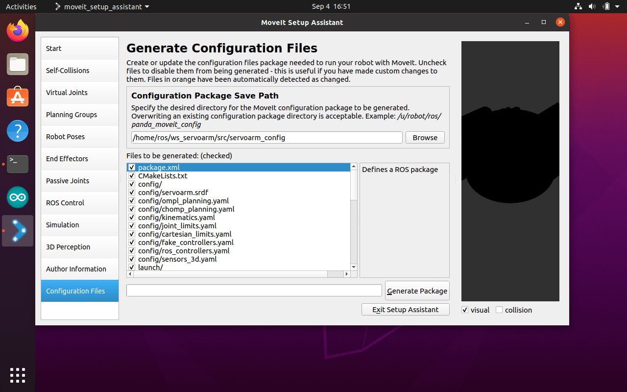
MoveIt Setup Assistant
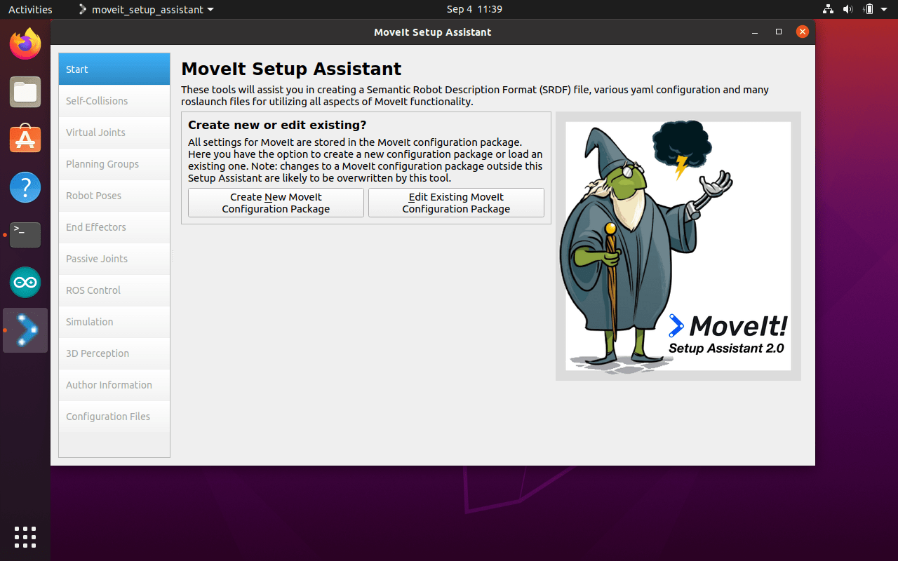
One nice thing about MoveIt is it has a graphical setup assistant. The assistant is a graphical user interface for configuring any robot for use with MoveIt. Its primary function is generating a Semantic Robot Description Format (SRDF) file for your robot. Additionally, it generates other necessary configuration files for use with the MoveIt package. I initially created my ROS package into which I imagined I would place these generated files. However, I discovered that this assistant generates the whole package. So I had to delete my initial package and just generate the whole package from the assistant – really quite easy.
Full documentation for the MoveIt Setup Assistant can be reached by clicking this link.
I typed the following command to start the Assistant
roslaunch moveit_setup_assistant setup_assistant.launchI found that I had to open and close the Assistant many times to get the configuration I needed, so I created a bash script to save typing the command each time.
To create a new configuration, I had to browse to the URDF file I created in the first post (arm.urdf).

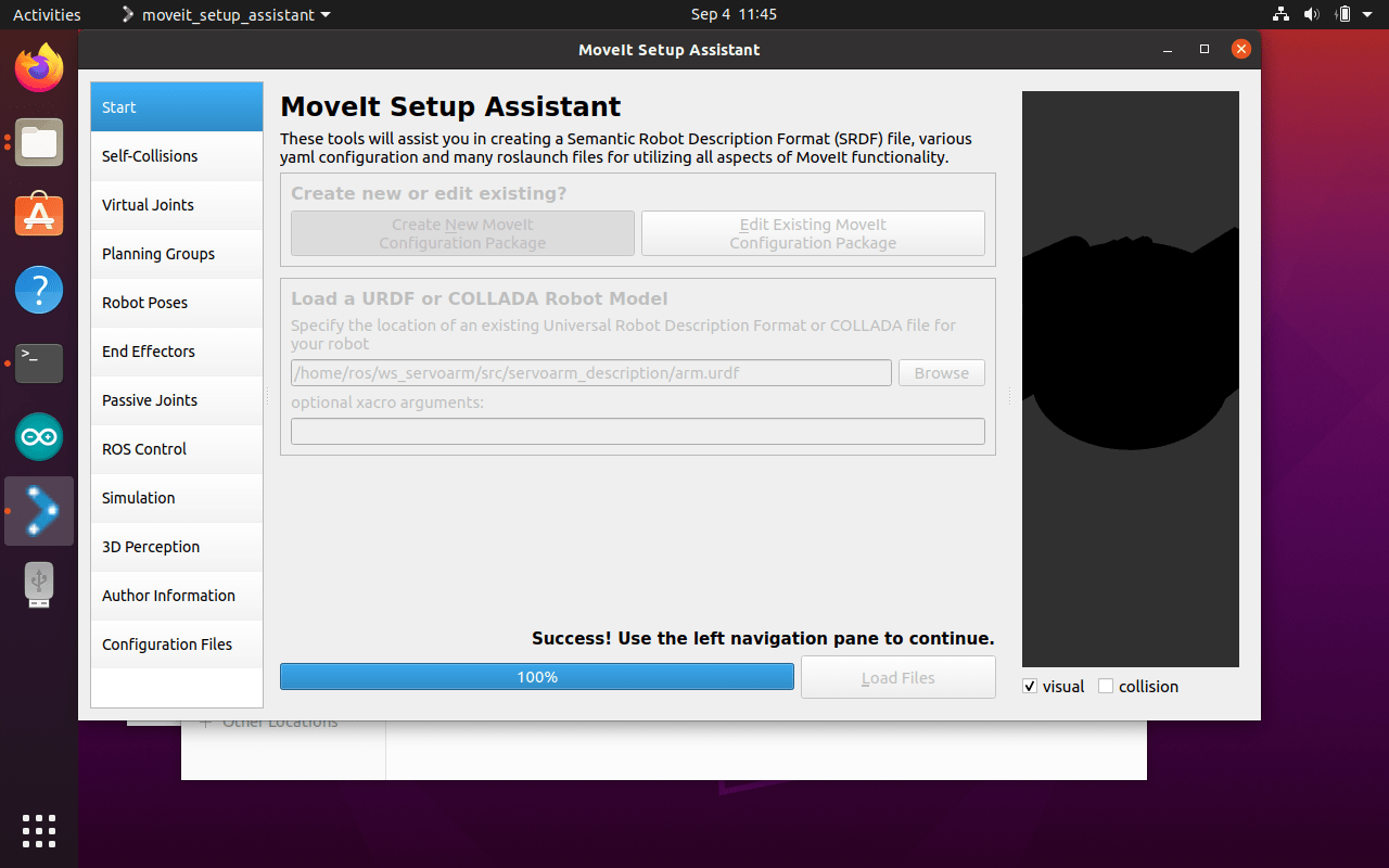
Once the URDF file had successfully loaded I was able to configure all the required components of MoveIt. The MoveIt website provides a pretty good description of how to configure the package, however, there was a couple of areas I had to experiment with as the path forward was not clear. I will give some details of these configurations.
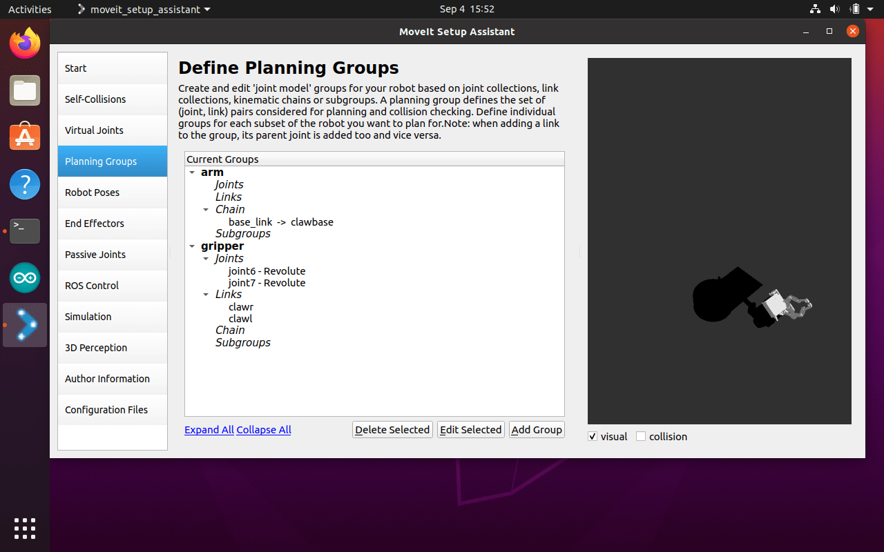
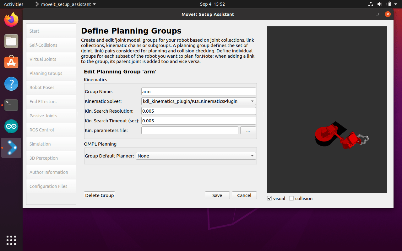
To start with, I generated the Self Collisions and created a Virtual Joint as per the instructions (I remember reading why – I think!). I then created the planning groups. The simulation environment uses these to understand what arm components are used for motion planning. I found there were a number of ways to configure this, and took quite a bit of research and playing to get this to work as I expected. So, for the arm I configured a Chain (no joints or links) and for the gripper I used joints and links. Also, I needed to set the kinematic solver. There are quite a few on this list, but the instructions directed to use the ‘kdi_kinematics_plugin’. Not sure what all the others do, maybe I will test and experiment at some stage in the future. I did not need to set a kinematic solver for the gripper. Obviously, as the gripper just opens and closes, any sophisticated kinematics is not needed.
I found that it took quite a bit of testing and adjusting the motion planning output and conversion for use by the Arduino to control the servos (I will detail later in this post). I created a number of Robot Poses in the Assistant to aid with configuration and debugging. I set a home pose (always a good place to start), a 0 degree and a 180 degree pose for each joint, plus a few other poses. This enabled me to debug the output of the planning and the radian conversion in the Arduino. Given I was using the serial port to communicate with the Arduino, I was not able to monitor the input or output of the Arduino. I finished up creating a new message node on the Arduino and sent messages back to ROS to see what was going on. Because, at the start it was not doing anything like what I expected. I will explain this more later.
Set robot poses to help with setup and debugging
Generate simulation package
Before I could run the simulation I needed to re-build the ROS environment.
cd ~/ws_servoarn

catkin_make
I was now ready to test if the simulation and motion planning did what I expected in RViz. To run the simulation I needed to run the following command.
roslaunch servoarm_config demo.launch rviz_tutorial:=trueWith quite a bit of luck I was able to see the following screen.
ROS MoveIt simulation within RViz
From this screen I was able to drag the gripper around the screen, and the robot arm simulation would move to support the new location. Then by clicking the ‘Plan & Execute’ button RViz would simulate the motion of the arm to the end location.
Setup Arduino
Now the fun bit started.
Up until now I had only been working in the virtual world (simulation), now I had to get the physical world to match and react to this virtual world. I planned to use an Arduino to control the robot arm. To do this the Arduino needed to be able to subscribe to messages published by ROS and MoveIt and translate them into messages a simple servo could understand. A servo can receive only one message, which is the required degrees of rotation between 0 and 180 – nothing else. You have no control over speed, it will just go to the specified angle at the speed designed into the servo.
I have setup the Arduino IDE on a Windows PC and Mac many times, but this was the first time on Linux. Like almost everything on Linux there seems to be many ways to do this, with varying Arduino versions and packages available. I was also planning to setup a ROS node on the Arduino using ‘rosserial’. A quote from the ROS wiki – “rosserial is a protocol for wrapping standard ROS serialized messages and multiplexing multiple topics and services over a character device such as a serial port or network socket”. Seems like it should do the job.
I found that not all packages and libraries worked together. At one stage I upgraded the rosserial library when a new version popped up on the IDE, and every thing stopped with a lot of confusion and loud messages. So rather than fix the problem, I just reinstalled the old library on the Arduino. One day I might go back and try and get everything working on the latest versions.
These are the versions I am using: Arduino IDE – 1.8.15, Rosserial Arduino Library – 0.7.9, and Adafruit PWM Servo Driver Library – 2.4.0.
My Arduino code can be downloaded from github. Click on this link to view the code.
The code is pretty straight forward. The Arduino subscribes to the ‘joint_states’ message, which is published by MoveIt. This message gives the angle state for each joint as the robot arm moves along the planned path to the desired position. This is sent as an array and the angles are in radians. The Arduino code then converts each joint to degrees. Some of the angles were 90 degrees out (not sure if I made a mistake in the URDF or simulation setup) but I had to add or subtract 90 degrees from some of the joint angles. This is where the debug message came in handy. In this architecture the Arduino’s serial port is being used by rosserial, so it is not possible to run the serial monitor to see what is happening on the Arduino. I don’t know about anyone else, but I do not find radians very intuitive and I was not sure if the angles being produced aligned to what I assumed the servos would need. I created a rosserial publish message on the Arduino and sent the servo degrees back to ROS. This way I could send the simulator to a particular pose (see Setup Assistant above) and check if the correct angles are being produced by the Arduino. I needed to get this all correct before I connected the robot, and had a robot arm flying about unexpectedly.
For more details on rosserial, click on this link to go to the ROS wiki – rosserial.
I typed the following commands in separate terminals.
roslaunch servoarm_config demo.launch rviz_tutorial:=truerosrun rosserial_python serial_node.py _port:=/dev/ttyUSB0 _baud:=115200rostopic echo /joint_statesrostopic echo /servoarm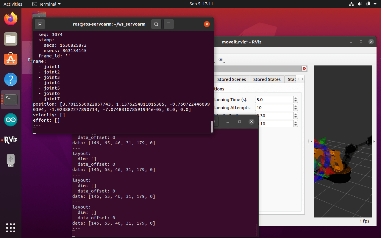

Once I was comfortable that the servo angles were as I expected, I connected the robot to the Arduino. I was able to drag the arm about in RViz or select a pose, then clicked the ‘Plan & Execute’ button, and much to my surprise the robot arm moved to the location and pose shown in the simulator.
This is not a high precision robot arm, but the end result was not to bad. The movement is a bit jumpy, but that is to be expected as the servos are all being moved a small amount each time a message is received. I will need to play with the speed parameter and with the kinematic solver to get a smoother motion. Sometimes a resonate type vibration developed, I will also need to play with the Arduino to smooth this out. You may see some jumps in the video. It turned out that I am not a very good robot arm driver, and I kept on knocking over the rear panel. I edited this out.
ROS MoveIt RViz simulation drives robot arm
The range of motion of the servos is not exactly 180 degrees, so I have added some angle adjustments in the Arduino code to make the simulation and reality better aligned.
Conclusion
I am quite pleased that this all actually worked. Clearly it needs some fine tuning, including a more stable base. But I managed to install MoveIt, configure it for my robot, install the Arduino code including rosserial, connect the Arduino to the robot arm, and actually move the robot arm from within ROS and MoveIt.
In the next post I intend try a few extra things with the robot arm. Create a python package to drive the robot, perhaps pick and stack some blocks. Also, connecting ROS over the serial port is quite physically restricting (also a bit old fashion). I was thinking of trying to use MQTT to send the ROS messages to the Arduino. At least this could be wireless, and it could enable integration with other IoT technology. Also, I have a lot more experience with IoT.

Sir, I just manage to modify your code to build a robot using 18 servos and arduino uno board of my own for graduation project, yet after successful serial connection it said that “Message from ROS network dropped: Message larger than buffer.” I tried to change the .h files in the roslib of arduino but it didn’t worked. How could I solve this issue?
I would highly appreciate it if you can help me on this one.
And here is the arduino code:
#include “Wire.h”
#include
#define SERVOMIN 102 // This is the ‘minimum’ pulse length count (out of 4096)
#define SERVOMAX 512 // This is the ‘maximum’ pulse length count (out of 4096) MID:307
#define MIN_PULSE_WIDTH 500
#define MAX_PULSE_WIDTH 2500
#define FREQUENCY 50
// called this way, it uses the default address 0x40
Adafruit_PWMServoDriver pwm1 = Adafruit_PWMServoDriver(0x40);
Adafruit_PWMServoDriver pwm2 = Adafruit_PWMServoDriver(0x41);
#include “Arduino.h”
#include “ArduinoHardware.h”
#include
#include
#include
#include
// Set ROS – handler, subscribe message, publish message (debugging)
ros::NodeHandle nh;
std_msgs::Int16MultiArray str_msg2;
ros::Publisher chatter(“warp_wraith”, &str_msg2);
int servoDegree[18];//joints
// Define Servo Outputs on first PCA9685 board(a,b,c)
int leg_a0 = 0;
int leg_a1 = 1;
int leg_a2 = 2;
int leg_b0 = 3;
int leg_b1 = 4;
int leg_b2 = 5;
int leg_c0 = 6;
int leg_c1 = 7;
int leg_c2 = 8;
// Define Servo Outputs on second PCA9685 board(a,b,c)
int leg_d0 = 9;
int leg_d1 = 10;
int leg_d2 = 11;
int leg_e0 = 12;
int leg_e1 = 13;
int leg_e2 = 14;
int leg_f0 = 15;
int leg_f1 = 16;
int leg_f2 = 17;
// Define Motor position variables on first PCA9685 board(a,b,c)
double mtrDegreeleg_a0;
double mtrDegreeleg_a1;
double mtrDegreeleg_a2;
double mtrDegreeleg_b0;
double mtrDegreeleg_b1;
double mtrDegreeleg_b2;
double mtrDegreeleg_c0;
double mtrDegreeleg_c1;
double mtrDegreeleg_c2;
// Define Motor position variables on second PCA9685 board(a,b,c)
double mtrDegreeleg_d0;
double mtrDegreeleg_d1;
double mtrDegreeleg_d2;
double mtrDegreeleg_e0;
double mtrDegreeleg_e1;
double mtrDegreeleg_e2;
double mtrDegreeleg_f0;
double mtrDegreeleg_f1;
double mtrDegreeleg_f2;
// Function move motor to ROS angle
void servo_cb(const sensor_msgs::JointState& cmd_msg)
{
mtrDegreeleg_a0 = trimLimits(radiansToDegrees(cmd_msg.position[0]));//mtrDegreeleg_a0 = trimLimits(radiansToDegrees(cmd_msg.position[0]) – 90);
mtrDegreeleg_a1 = trimLimits(radiansToDegrees(cmd_msg.position[1]));
mtrDegreeleg_a2 = trimLimits(radiansToDegrees(cmd_msg.position[2]));
mtrDegreeleg_b0 = trimLimits(radiansToDegrees(cmd_msg.position[3]));
mtrDegreeleg_b1 = trimLimits(radiansToDegrees(cmd_msg.position[4]));
mtrDegreeleg_b2 = trimLimits(radiansToDegrees(cmd_msg.position[5]));
mtrDegreeleg_c0 = trimLimits(radiansToDegrees(cmd_msg.position[6]));
mtrDegreeleg_c1 = trimLimits(radiansToDegrees(cmd_msg.position[7]));
mtrDegreeleg_c2 = trimLimits(radiansToDegrees(cmd_msg.position[8]));
mtrDegreeleg_d0 = trimLimits(radiansToDegrees(cmd_msg.position[9]));
mtrDegreeleg_d1 = trimLimits(radiansToDegrees(cmd_msg.position[10]));
mtrDegreeleg_d2 = trimLimits(radiansToDegrees(cmd_msg.position[11]));
mtrDegreeleg_e0 = trimLimits(radiansToDegrees(cmd_msg.position[12]));
mtrDegreeleg_e1 = trimLimits(radiansToDegrees(cmd_msg.position[13]));
mtrDegreeleg_e2 = trimLimits(radiansToDegrees(cmd_msg.position[14]));
mtrDegreeleg_f0 = trimLimits(radiansToDegrees(cmd_msg.position[15]));
mtrDegreeleg_f1 = trimLimits(radiansToDegrees(cmd_msg.position[16]));
mtrDegreeleg_f2 = trimLimits(radiansToDegrees(cmd_msg.position[17]));
// Store motor movements for publishing back to ROS (debugging)
servoDegree[0] = mtrDegreeleg_a0;
servoDegree[1] = mtrDegreeleg_a1;
servoDegree[2] = mtrDegreeleg_a2;
servoDegree[3] = mtrDegreeleg_b0;
servoDegree[4] = mtrDegreeleg_b1;
servoDegree[5] = mtrDegreeleg_b2;
servoDegree[6] = mtrDegreeleg_c0;
servoDegree[7] = mtrDegreeleg_c1;
servoDegree[8] = mtrDegreeleg_c2;
servoDegree[9] = mtrDegreeleg_d0;
servoDegree[10] = mtrDegreeleg_d1;
servoDegree[11] = mtrDegreeleg_d2;
servoDegree[12] = mtrDegreeleg_e0;
servoDegree[13] = mtrDegreeleg_e1;
servoDegree[14] = mtrDegreeleg_e2;
servoDegree[15] = mtrDegreeleg_f0;
servoDegree[16] = mtrDegreeleg_f1;
servoDegree[17] = mtrDegreeleg_f2;
moveMotorDeg(mtrDegreeleg_a0, leg_a0);
moveMotorDeg(mtrDegreeleg_a1, leg_a1);
moveMotorDeg(mtrDegreeleg_a2, leg_a2);
moveMotorDeg(mtrDegreeleg_b0, leg_b0);
moveMotorDeg(mtrDegreeleg_b1, leg_b1);
moveMotorDeg(mtrDegreeleg_b2, leg_b2);
moveMotorDeg(mtrDegreeleg_c0, leg_c0);
moveMotorDeg(mtrDegreeleg_c1, leg_c1);
moveMotorDeg(mtrDegreeleg_c2, leg_c2);
moveMotorDeg(mtrDegreeleg_d0, leg_d0);
moveMotorDeg(mtrDegreeleg_d1, leg_d1);
moveMotorDeg(mtrDegreeleg_d2, leg_d2);
moveMotorDeg(mtrDegreeleg_e0, leg_e0);
moveMotorDeg(mtrDegreeleg_e1, leg_e1);
moveMotorDeg(mtrDegreeleg_e2, leg_e2);
moveMotorDeg(mtrDegreeleg_f0, leg_f0);
moveMotorDeg(mtrDegreeleg_f1, leg_f1);
moveMotorDeg(mtrDegreeleg_f2, leg_f2);
}
ros::Subscriber sub(“joint_states”, servo_cb);
void setup()
{
// Setup ROS fir subscribe and publish
nh.getHardware()->setBaud(115200);
nh.initNode();
nh.subscribe(sub);
nh.advertise(chatter);
// Setup PWM Controller object
pwm1.begin();
pwm1.setPWMFreq(FREQUENCY);
pwm2.begin();
pwm2.setPWMFreq(FREQUENCY);
}
// Function to move motor to specific position
void moveMotorDeg(int moveDegree, int motorOut)
{
int pulse_wide, pulse_width;
// Convert to pulse width
pulse_wide = map(moveDegree, 0, 320, MIN_PULSE_WIDTH, MAX_PULSE_WIDTH);
pulse_width = int(float(pulse_wide) / 1000000 * FREQUENCY * 4096);
//Control Motor
//use while two classifi the two board 2022/9/19
while(motorOut = 9)
{
pwm2.setPWM(motorOut-9, 0, pulse_width);
}
}
void loop()
{
str_msg2.data = servoDegree;
str_msg2.data_length = 18;//all servo data message
chatter.publish( &str_msg2 );
nh.spinOnce();
}
// Convert radians to degreees
double radiansToDegrees(float position_radians)
{
position_radians = position_radians * 57.2958;
return position_radians;
}
// Sometimes servo angle goes just above 320 or just below 0 – trim to 0 or 320
double trimLimits(double mtr_pos)
{
if(mtr_pos > 320) {
mtr_pos = 320;
}
if(mtr_pos < 0) {
mtr_pos = 0;
}
return mtr_pos;
}
Hi – Not sure what is causing this problem. It is a lot of servos (and therefore ROS messages) to process/run. Have you got it working with just one (or just a few) servos and one driver board to see if it all work? – I have no experience with more than one driver board. I would try and simplify and get working with a simple architecture and then expand, to see where the system breaks.
Regards
Ken