Simple robot arm controlled by ROS and MoveIt – Part 1
Build, 3D Model and ROS Simulation (urdf)
As I mentioned on the project page of this site, my aim is to use a simple servo based robot arm to learn how ROS can be used to drive a robot arm. I hope that this will help me build something a little more sophisticated in the future.
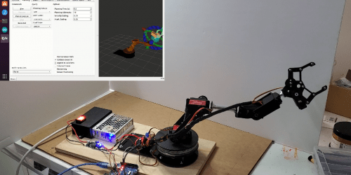
This post will describe the start of my journey to build a ROS driven servo based robot arm. I have started by buying a 6 DOF (Degrees Of Freedom) servo based robot arm kit. I then modelled the arm in Fusion 360. The 3D model provided all the components required to create the robot simulation within ROS. A URDF file was required to describe the model for use in the ROS simulation. I will give you access to my 3D model, the simulation model components and the URDF file. I then created a manual simulation of the model to ensure that all components appear correct and operate correctly.
The Robot Operating System (ROS) is an opensource environment that helps build robot applications. ROS has a number of packages that provide the algorithms and tools to drive a robot arm. For further information on ROS click here. If you are looking at the ROS site – I have used the Noetic release of ROS.
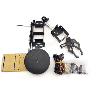
I bought a simple servo based robot arm from AliExpress (6 DOF Rotating Base Robot Manipulator Metal Alloy Mechanical Arm Clamp Claw Bracket Kit). I selected this kit as it had a proper split ring bearing to support the base of the robot arm – hopefully it would give more stability while rotating. The kit does not come with servos, and I selected some stronger servos for the lower three joints than was recommended for the kit – they seemed low powered, and there was a number of suggestions on the web to upgrade to more powerful servos.
3 x 25KG Metal Steering Digital Waterproof Servo DS3225mg
3 x MG995 180° High Torque Metal Gear RC Servo Motor
The kit seems of reasonable quality and is quite professionally finished. However, the kit comes with no instructions, so it took a few reworkings to make sure all the brackets, servos and components aligned correctly.
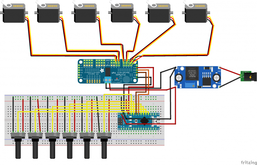
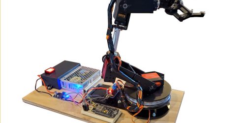
I used a PCA9685 16 Channel 12-bit PWM Servo motor Driver I2C Module to drive the servos from the Arduino, this makes it much simpler to wire up all the servos on the arm. Also, I used an Arduino Nano as it has two more analog pins than a Uno – I needed these pins, as two pins are used for the I2C interface. When I move to a ROS controller, I will not need all those pins, and a Uno will be fine.
I don’t intend to give a detailed instruction on how to build the model. There are quite a few sites that give detailed instructions on how to build similar models. The DroneBot Workshop YouTube channel provides very detailed instructions on how to build a similar robot arm.
A couple of suggestions:
- Build a potentiometer based rig to test and align each servo. See overview diagram below.
- Start at the base of the model – align and test each servo before you progress to the next part of the arm. Its highly likely that the components may not be properly aligned to start with, and you don’t want to be disassembling components to fix alignment problems.
- It is ESSENTIAL for your own safety, and the well being of your fingers that you mark the center point on each potentiometer with a permanent marker. When you power up the model it will immediately swing to the status of each potentiometer. I make sure that all potentiometers are set to the marked mid point before power on – which means the arm will move to the safety of the upright position.
- I used a couple of drops of silicone sealant to fix the top and bottom plates of the split ring bearing.
This diagram provides an overview of the rig I have built, to test the base operation of the robot arm.
The Arduino code can be viewed and downloaded here.
This is a very simple test code with no fancy bells and whistles. If you want to have manual joystick control of the robot, then a more sophisticated Arduino app would be required. At least this app should give you a few ideas.
The cheap potentiometers I had in my spare parts box are not very stable, so I had to add some code to reduce the flutter in the arm. I only intend to use this rig to test the function of the servos, and it will be replaced by a ROS controller in the next post.
All of the servos seem to work ok, and the robot arm moved as expected. This is not the smoothest robot arm of all time, but given it is being driven by relatively cheap hobby servos it seems that it will do the job. I needed to remind myself that the aim of this exercise is to learn more about how I can use ROS to drive and operate a robot arm.
Manual test of robot arm
It turns out that most of the vibration in the arm was due to the potentiometers – I put the serial monitor on the Arduino, and the signal from the pots was all over the place. The slightest touch or movement caused the signal to bounce quit a lot – also the pots were just pushed into the breadboard with very poor connections. But given the pots will be replaced by ROS, I did not put any effort into smoothing the signal.
It was important to remember to mark the center of each pot, and set before I powered up. When I powered on, each servo would immediately race to the point set by each pot. On one occasion I had the arm lying flat on the table, and when I powered the arm on, the arm swung by over 100 degrees and wiped quite a few things off the table – very dangerous.
3D Model
ROS has two simulation environments – RViz and Gazebo. This enabled me to build and test the software for the robot before I connected it to the physical robot arm. I used RViz as it comes preinstalled in the desktop version of ROS.
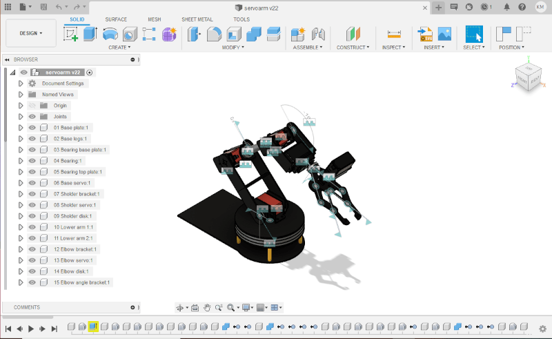
To create a simulation of the robot in ROS, I needed to create a 3D model of the overall robot, and then I used the model to create a model of each of the components of the robot arm. I created a 3D model of the robot arm in Fusion 360. The components and the joints have all been modelled. I did not go to the trouble of adding all the nuts and bolts, as this model is only for use in the ROS simulation. I did go to the trouble of creating all the joints in the model, including all the joints in the gripper. I created a “motion link” in the second gear component in the gripper to simulate the drive of the gear. This was all very nice, but I discovered that Fusion 360 does not use these joints in the Animation, and I had to remodel some of the joints within the Animation area. Also, given I plan to build the URDF file from scratch the joint modelling was of no value for creation of the components for the ROS simulation. Anyway, I learnt quit a bit about joints in Fusion 360.
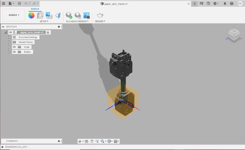
I then exported each of the components of the model (STL format) as meshes for reference by the URDF file. If you intend to change my model to suit your particular robot arm, make sure you center the rotational axis of the component on the axis of the origin of the model. I exported each component (mesh) of the robot, then re-imported each mesh and centered the rotational axis with an origin axis. This will make life a lot easier when creating and testing the URDF file.
Out of interest I created an animation of the model in Fusion 360. I wanted to find out how animations work in Fusion 360. Given I had to remodel all the joints in the animation, I only modelled some of the joints. Also, I only created a simplified mesh of the gripper, so that I could simply simulate the operation of the gripper – it seemed like too much work to fully simulate all the components of the gripper in URDF.
Fusion 360 animation of 3D model
ROS Simulation
The next task in this journey was to create a URDF file (xml description of the robot arm model), install ROS and manually test the functions of the model using RViz (simulation tool) from within ROS.
Install ROS
I installed ROS on Ubuntu 20.04.2 LTS which was running on VirtualBox VM on a Windows 10 PC. This is not the fastest environment in the world, but seems to run OK. I have run ROS in a similar environment before and it provided enough performance to run the ROS simulation packages (RViz and Gazebo). A ROS master or slave node will run on a Raspberry Pi, but it does not have enough power to run the visual simulation packages.
Once I set up Ubuntu I installed ROS Noetic. Detailed install instructions are available at the ROS wiki – Ubuntu install of ROS Noetic. I installed the ‘Desktop-Full’ package, as it includes the 3D simulation tools.
Once ROS was installed I created a workspace, called ws_servoarm. I then created a ROS package called servoarm_description. This is the package from where the URDF test app will be run. It will contain the meshes and URDF file (arm.urdf).
mkdir -p ~/ws_servoarm/src

cd ~/ws_servoarm

catkin_make

cd ~/ws_servoarm/src

catkin_create_pkg servoarm_description std_msgs

cd ~/ws_servoarm

catkin_make
If you are building your own robot – once the workspace and package have been created, copy the mesh and urdf file from my github repository (copy or clone)
Click here to go to my GitHub page.
URDF File
The URDF file (arm.urdf) contains an xml description of the model. It is divided into two main areas:
<link> – base_link, platform, lower_arm, top_arm, wrist, clawbase, clawr, clawl. This defines the physical components of the arm model. It references the corresponding mesh and sets the location in 3D space.
<joint> – there are seven joints. Each joint defines the relationship between each of the link components. It defines their location, the rotational axis and the rotational limits. The servos only have a 180 degree range of motion, and it is therefore important that this be defined to ensure a correct range of motion in the simulation. I simplified the action of the gripper, and have defined the joint for clawl as a <mimic> joint. The multiplier is set as -1 to enable each claw to operate in the opposite direction.
Launch Simulation
To run and test the functionality described in the URDF file I typed the following command from the same directory the arm.urdf file is located.
roslaunch urdf_tutorial display.launch model:=arm.urdfI also created a bash script (urdf.sh) in the ws_servoarm directory to make it easier to run and test the simulation.
Click here to download and view file.
The video below shows the operation of the RViz simulation of the model.
URDF file test in RViz simulation
Conclusion
So far so good – everything seemed to work ok. The main outcomes were the physical operation of the robot arm, and the simulation of the arm within ROS. In the next post, I intend to replace the manual (potentiometer) driver with a ROS based driver.
I intend to use Moveit, a ROS package that does all and more than I need to drive this simple robot arm. Moveit incorporates the latest advances in motion planning, manipulation, 3D perception, kinematics, control and navigation of robot arms. The main use I intend to deploy is the inverse kinematics capability (solve for joint positions for a given pose or gripper location), and then use the motion planning to move the arm to the required position. There are many more things that Moveit can do, but I think that if I can get this to work, it will be another positive step along my robot arm journey.
